
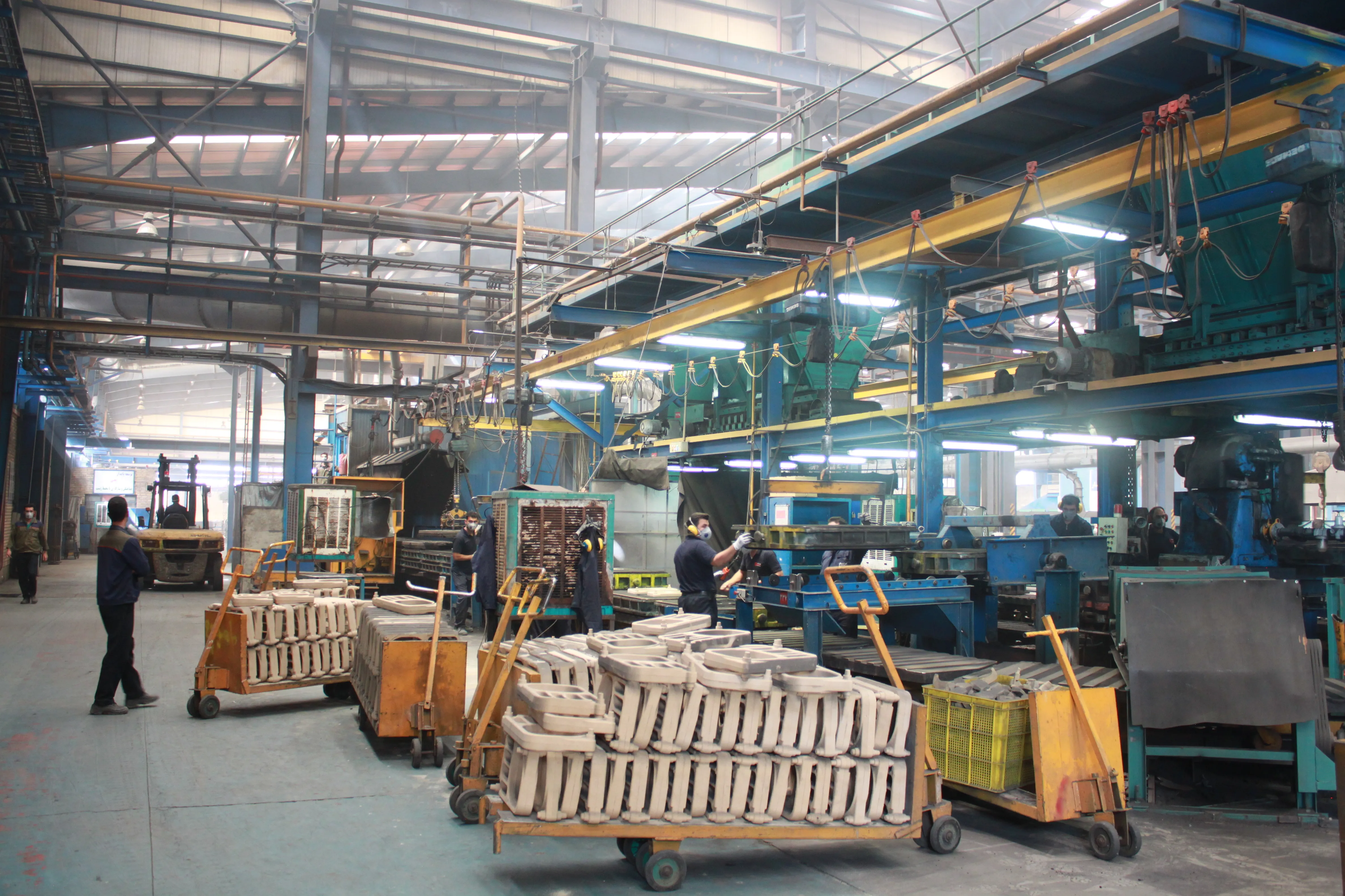
Manhole Covers
Solid Top Manhole Covers
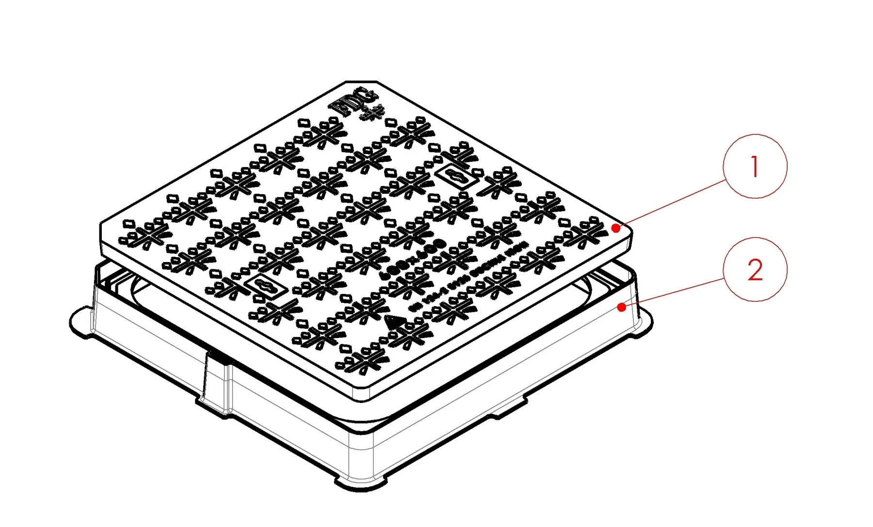
Single-piece covers in square and circular formats, from footway duty through to carriageway D400.
Solid Top
Ductile iron, EN 124 B125 / C250 / D400
The plain workhorse: one casting, one frame, no infill and no moving parts. Two ranges are published here — the GCC 600×600 in B125, C250 and D400, and the international range of seventeen models to EN 124-2, from 300×300 to 900×900 across the same three classes. The frame deepens with the load class it has to carry: on the 600×600, B125 seats in a 38 mm frame while C250 and D400 share a 100 mm frame, and every frame depth is published per model in the tables.
- Material
- Ductile iron GGG50 (EN-GJS-500-7), both ranges
- Standard
- EN 124-2
- Coating
- Bitumen as standard; epoxy on request
- Frame
- Depth follows the load class — 38 mm (B125) and 100 mm (C250/D400) on the 600×600; per-model depths in the international table
- Seating clearance
- 2 mm on the 600×600 models
- Options
- GRP sealing plate provision
Specifications
12 sizes, 3 load classes
Dimensions in millimetres. Sizes outside this range are produced to order.
GCC range
| Reference | Clear opening(mm) | Frame outer(mm) | Frame depth(mm) | Load class(EN 124) | Weight(kg) | Drawing |
|---|---|---|---|---|---|---|
| 600×600 Solid Top | 600 × 600 | 733 × 731 | 38 | B125 | 35 | 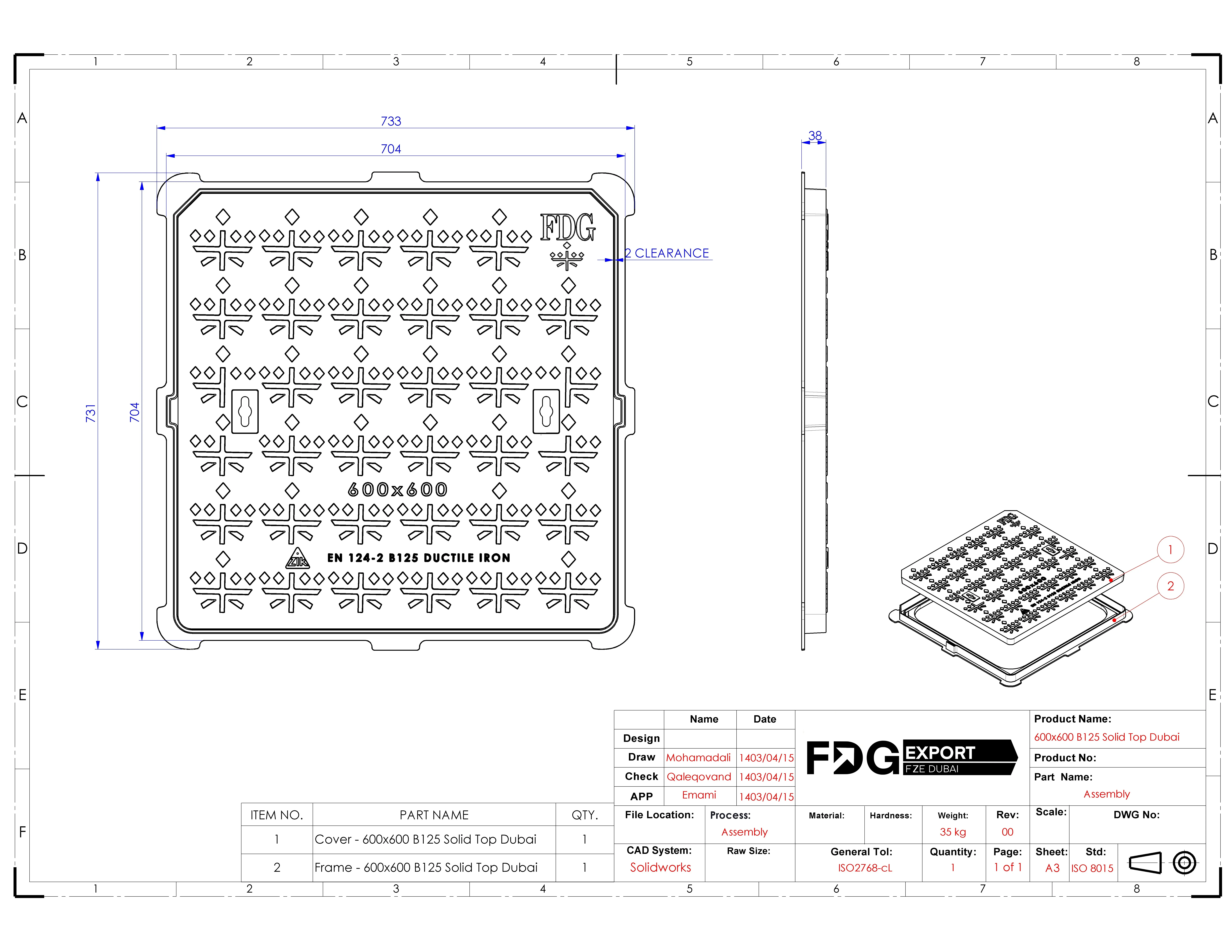 Preview only — contact us for the full drawing or DWG Preview only — contact us for the full drawing or DWG |
| 600×600 Solid Top | 600 × 600 | 733 × 731 | 100 | C250 | 55 | 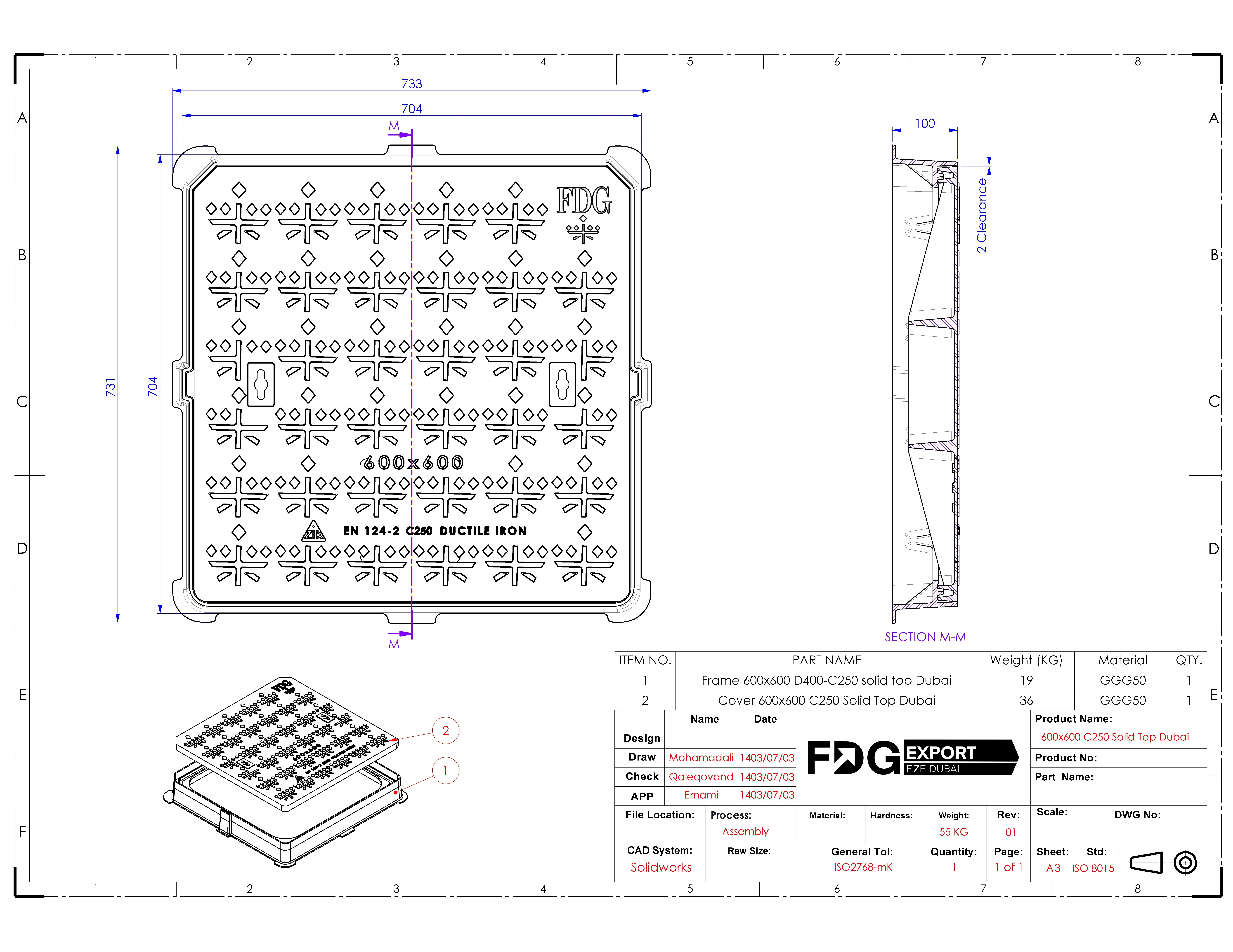 Preview only — contact us for the full drawing or DWG Preview only — contact us for the full drawing or DWG |
| 600×600 Solid Top | 600 × 600 | 733 × 731 | 100 | D400 | 63 | 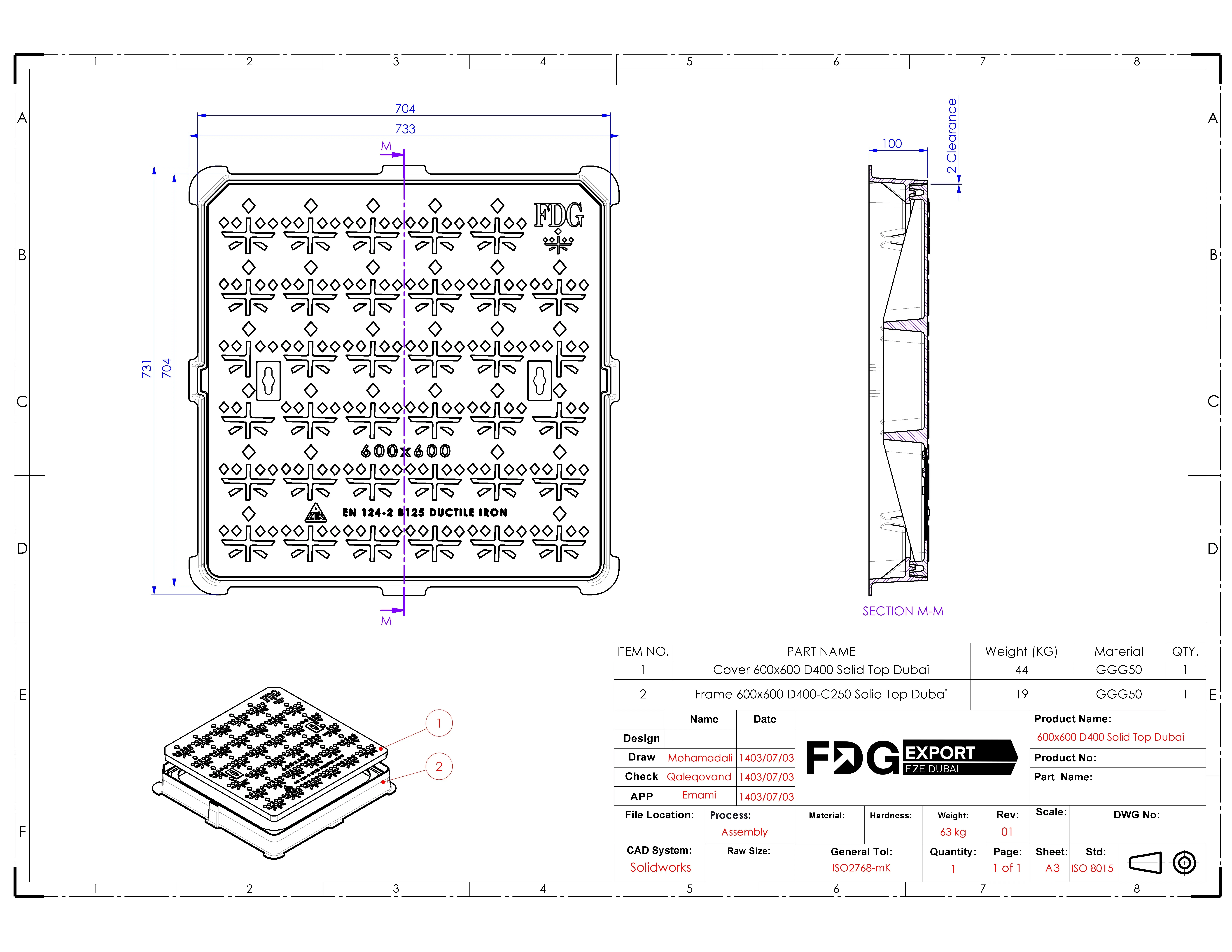 Preview only — contact us for the full drawing or DWG Preview only — contact us for the full drawing or DWG |
International range
| Reference | Clear opening(mm) | Frame outer(mm) | Frame depth(mm) | Load class(EN 124) | Weight(kg) | Drawing |
|---|---|---|---|---|---|---|
| FDG-B300 | 201 × 201 | 295 × 295 | 25 | B125 | 5.2 | 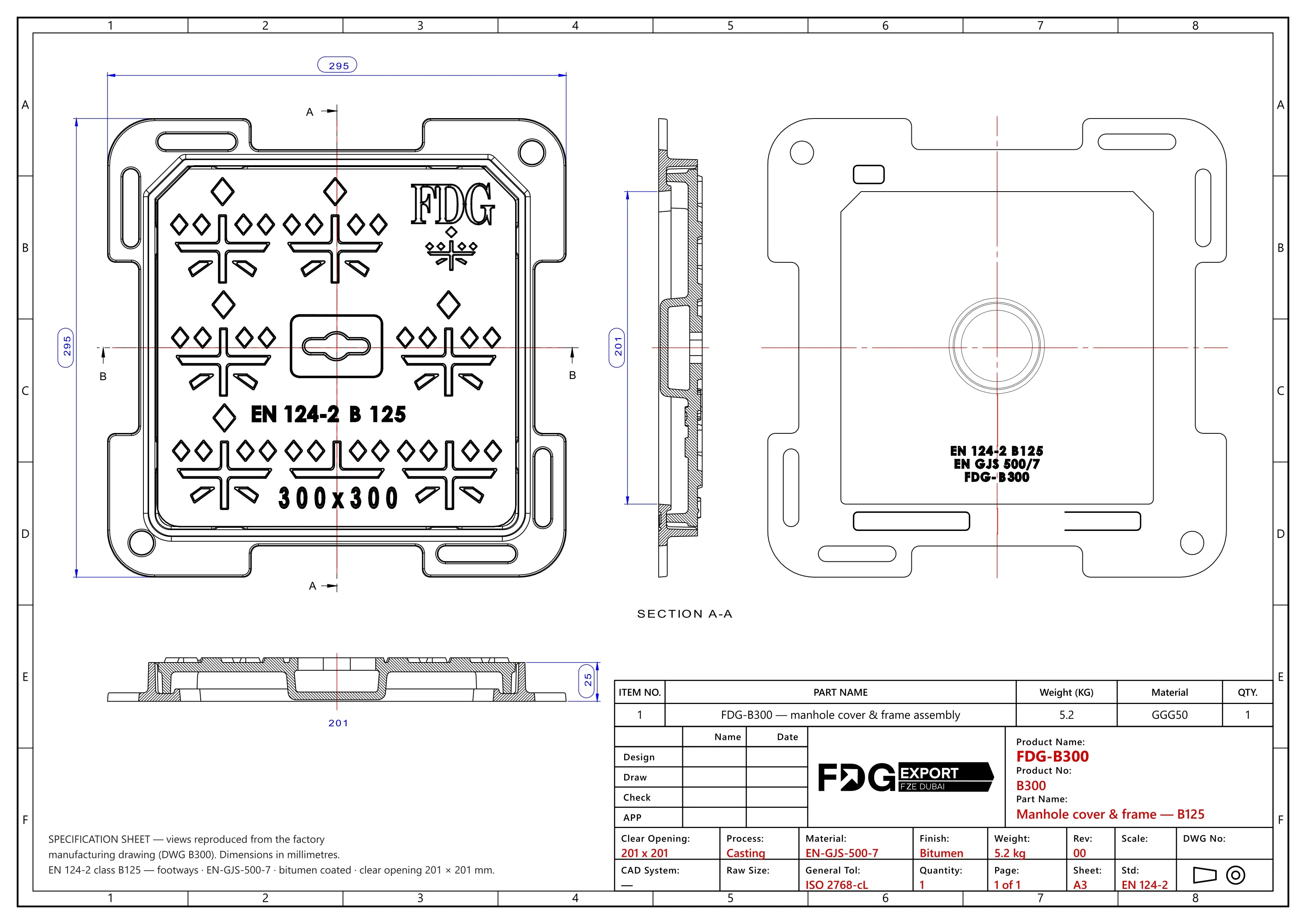 Preview only — contact us for the full drawing or DWG Preview only — contact us for the full drawing or DWG |
| FDG-B400 | 301 × 301 | 395 × 395 | 25 | B125 | 8.5 | 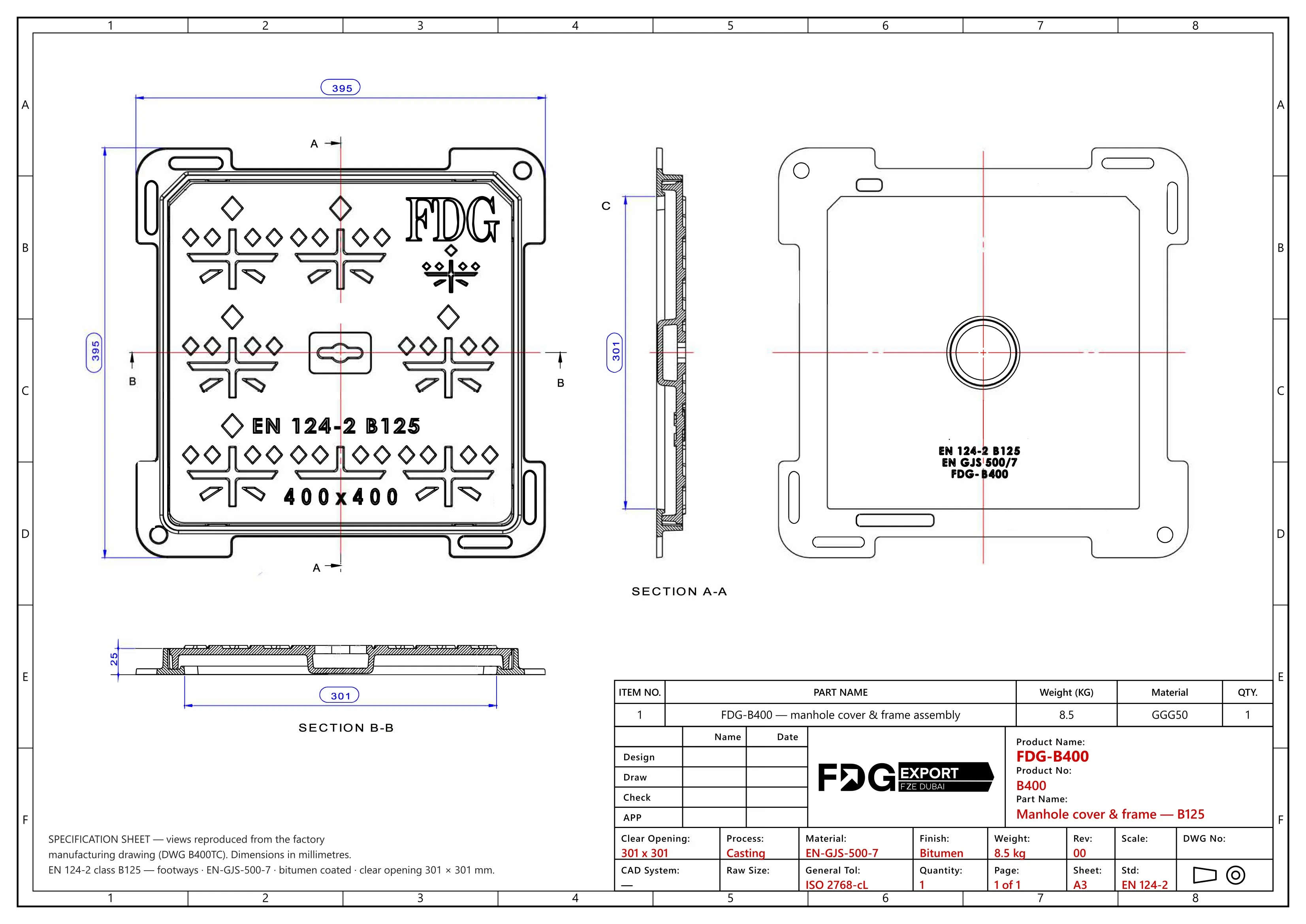 Preview only — contact us for the full drawing or DWG Preview only — contact us for the full drawing or DWG |
| FDG-B500 | 400 × 400 | 495 × 495 | 30 | B125 | 13.5 | 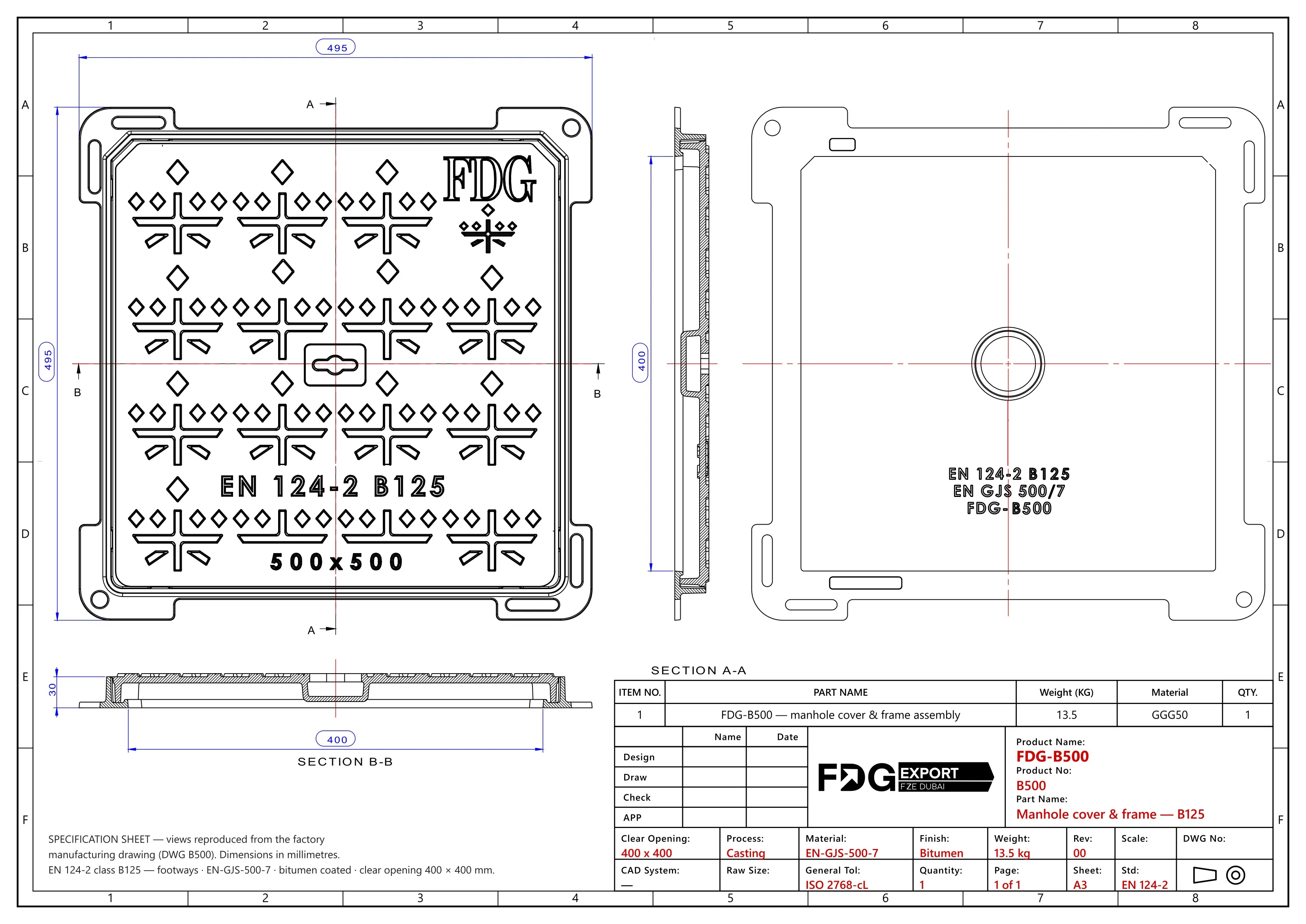 Preview only — contact us for the full drawing or DWG Preview only — contact us for the full drawing or DWG |
| FDG-B600 | 500 × 500 | 595 × 595 | 35 | B125 | 20.5 | 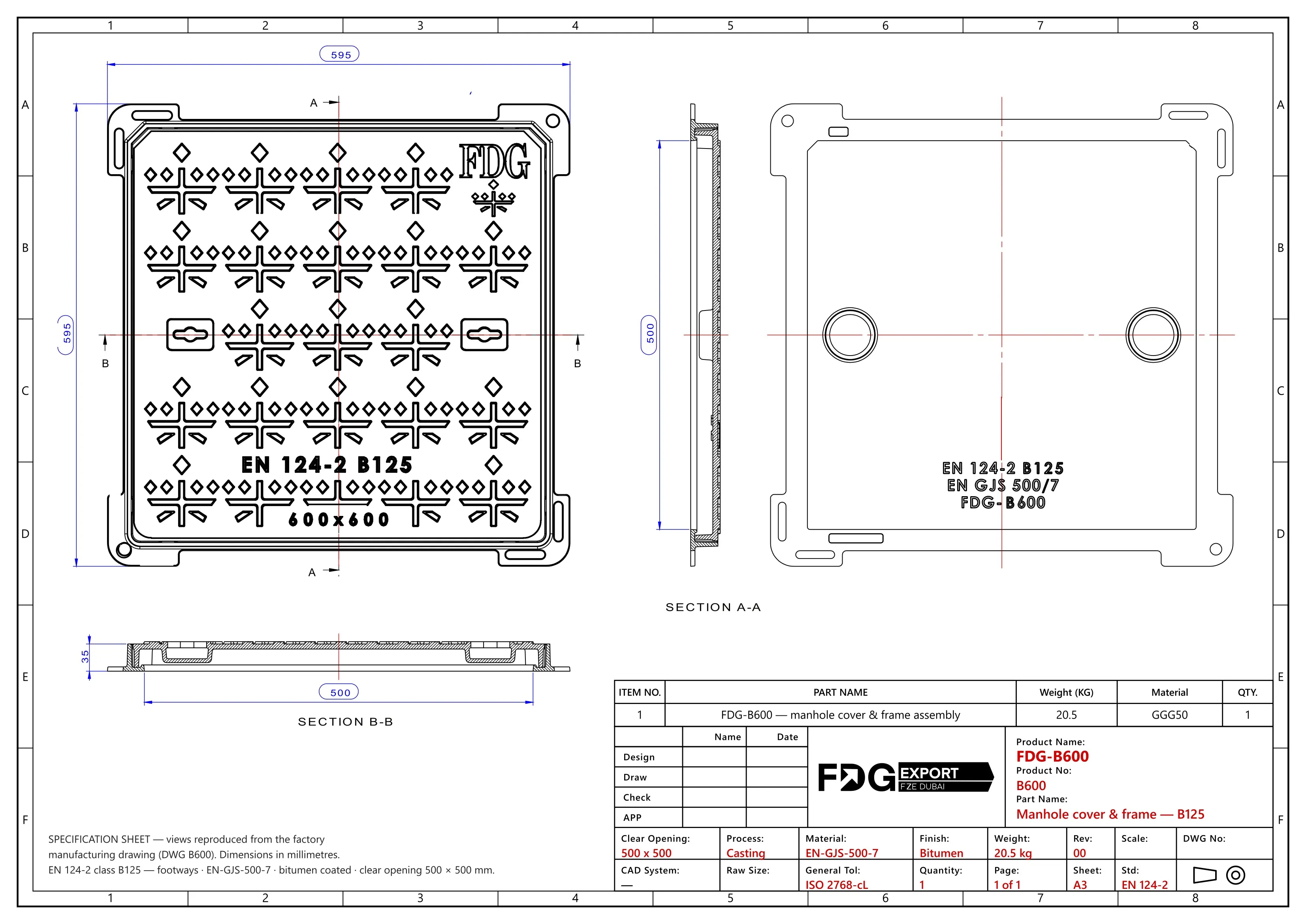 Preview only — contact us for the full drawing or DWG Preview only — contact us for the full drawing or DWG |
| FDG-B700 | 600 × 600 | 695 × 695 | 40 | B125 | 30.3 | 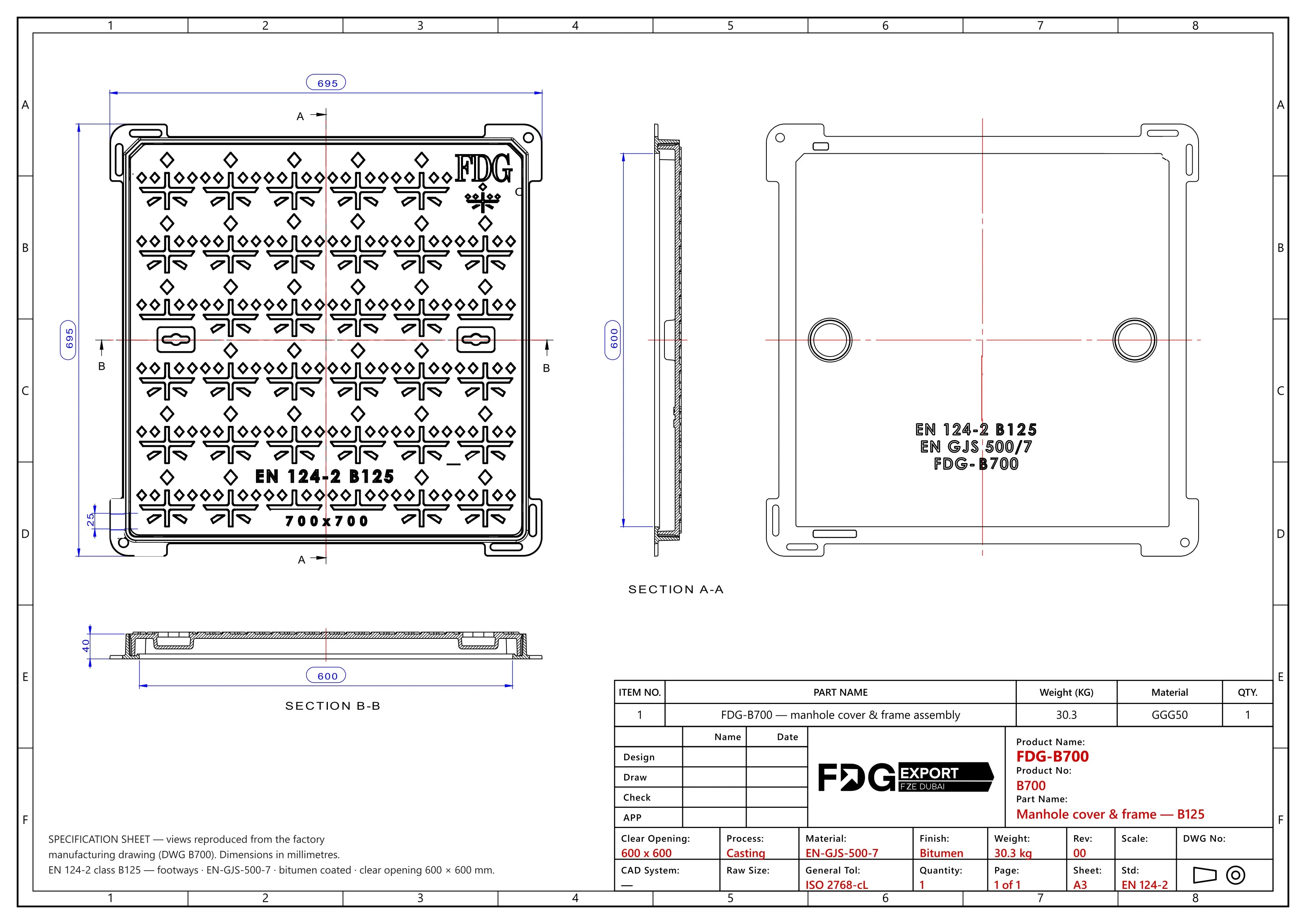 Preview only — contact us for the full drawing or DWG Preview only — contact us for the full drawing or DWG |
| FDG-C300 | 201 × 201 | 295 × 295 | 35 | C250 | 5.7 | 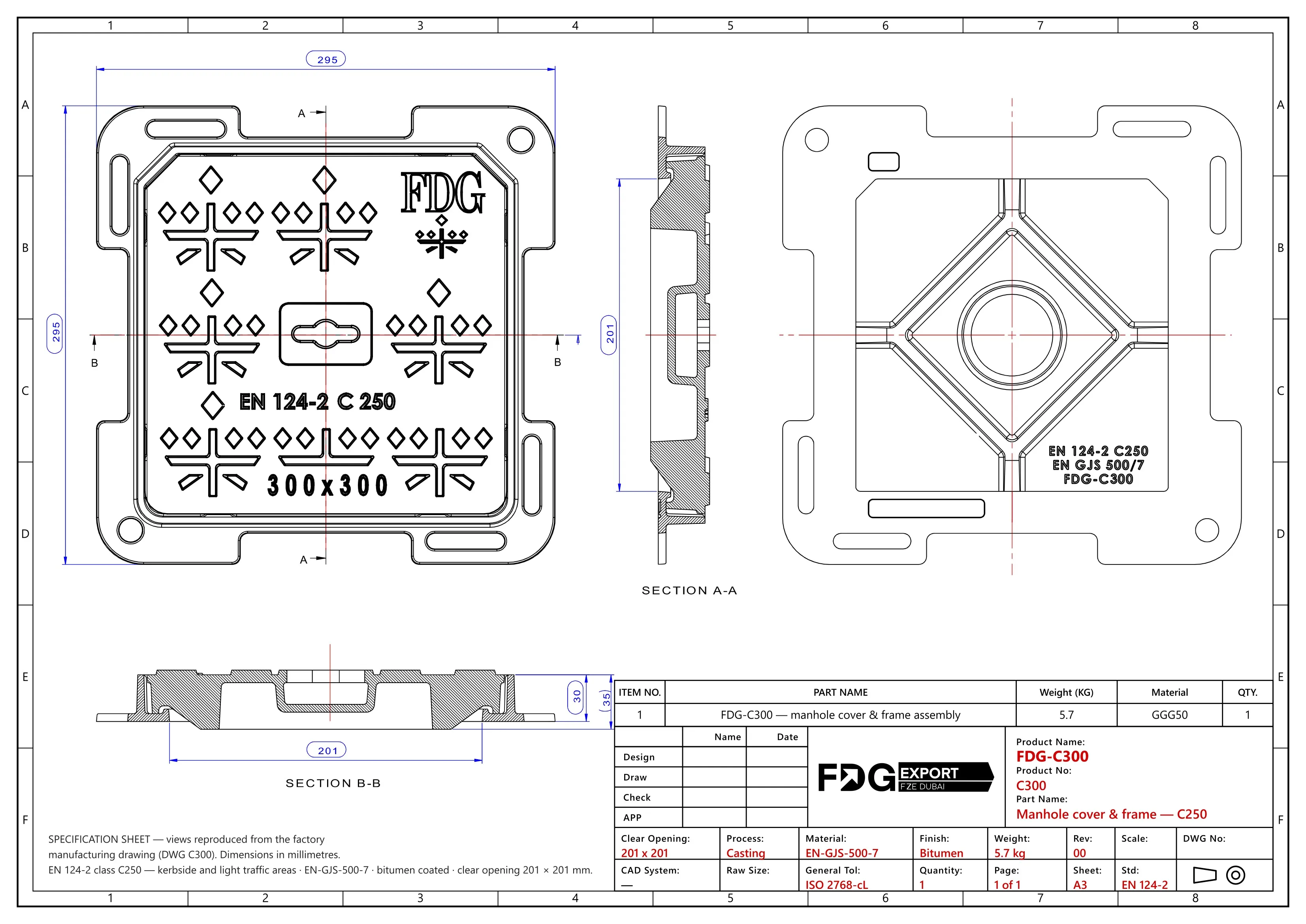 Preview only — contact us for the full drawing or DWG Preview only — contact us for the full drawing or DWG |
| FDG-C400 | 301 × 301 | 395 × 395 | 40 | C250 | 10.9 | 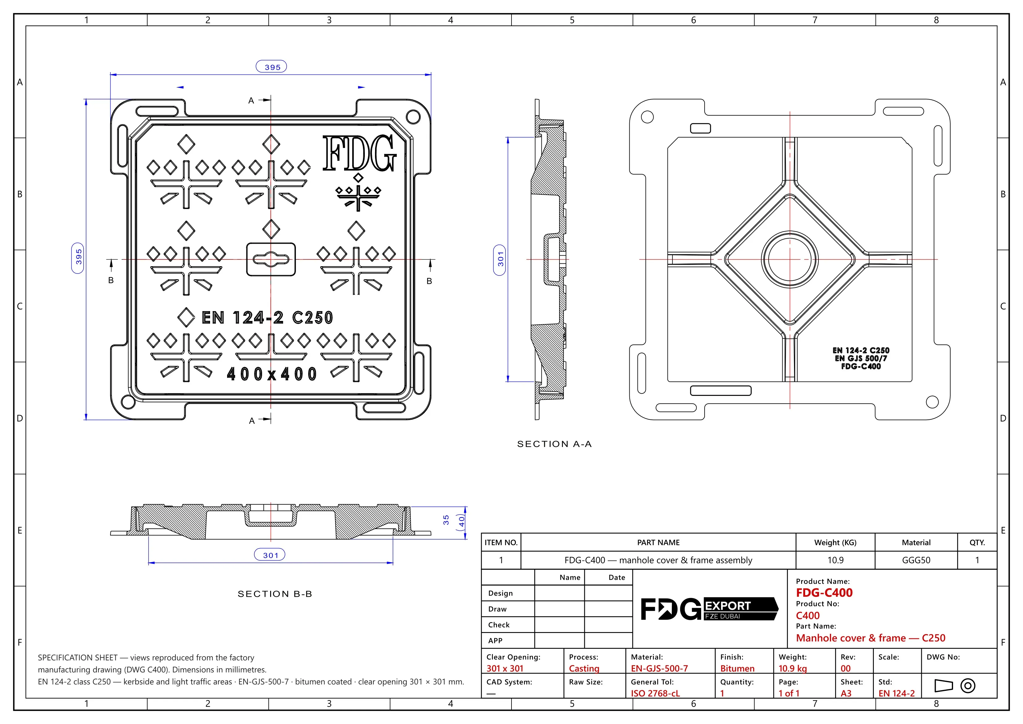 Preview only — contact us for the full drawing or DWG Preview only — contact us for the full drawing or DWG |
| FDG-C500 | 400 × 400 | 495 × 495 | 50 | C250 | 17.3 | 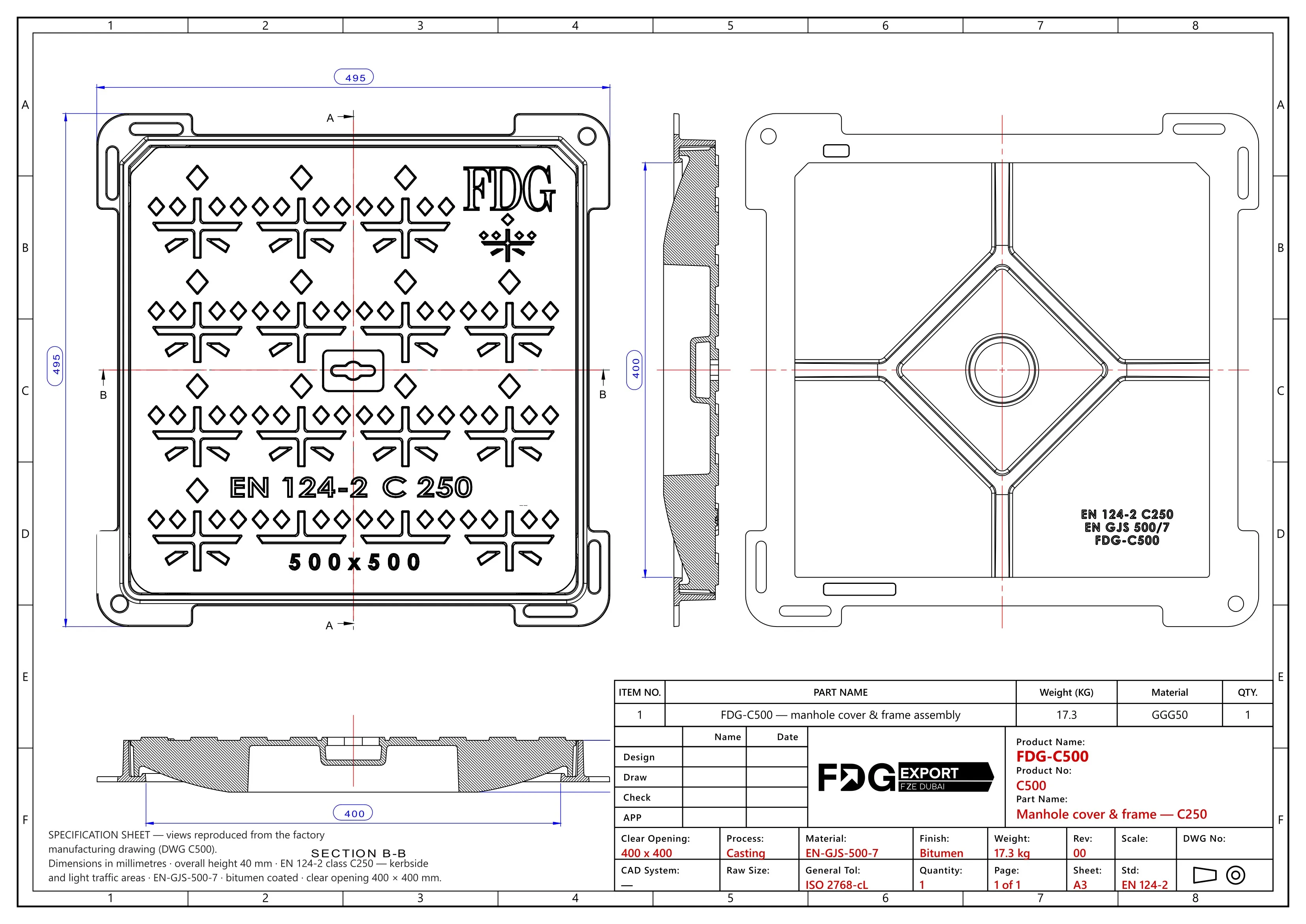 Preview only — contact us for the full drawing or DWG Preview only — contact us for the full drawing or DWG |
| FDG-C600 | 500 × 500 | 595 × 595 | 65 | C250 | 26.7 | 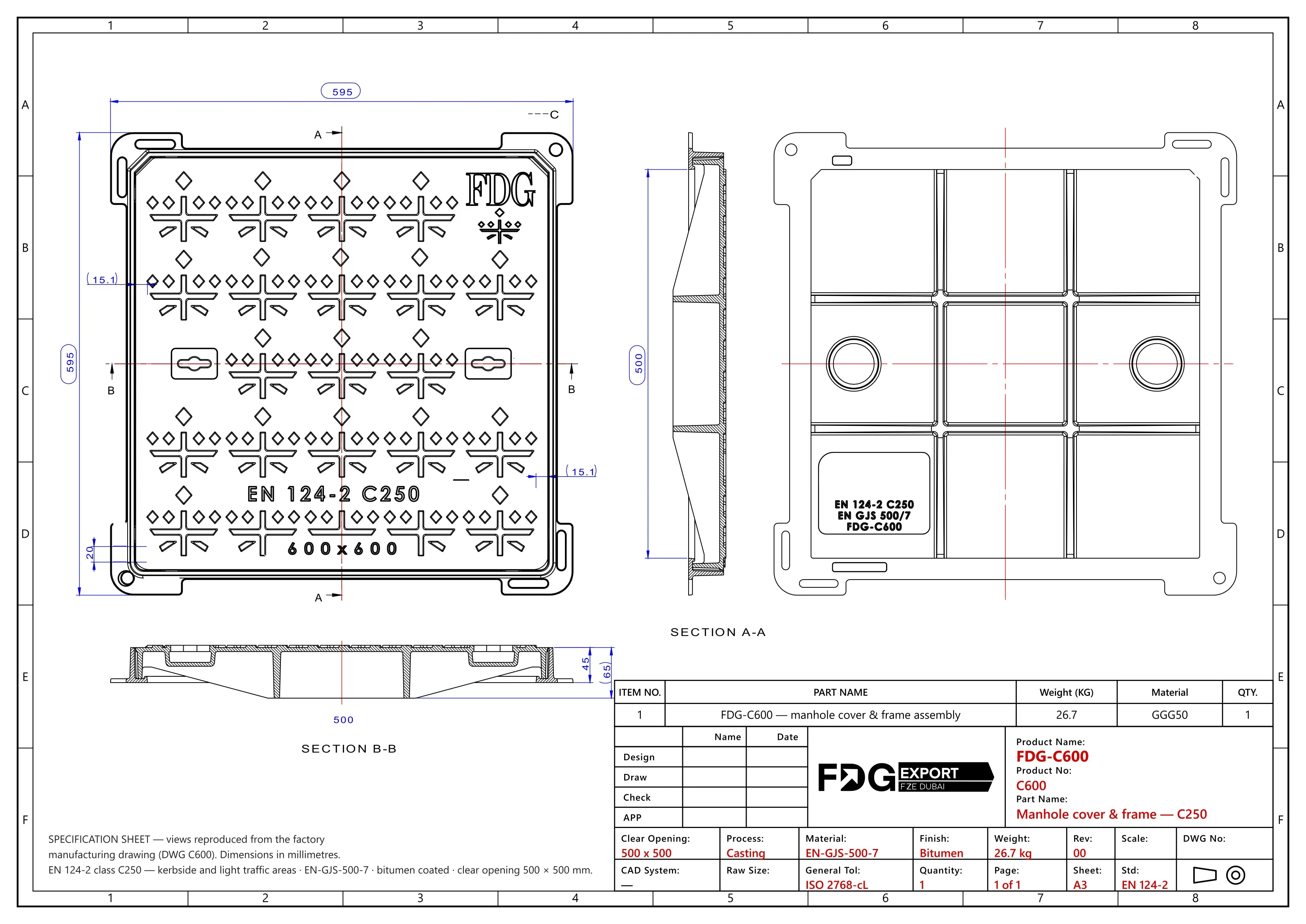 Preview only — contact us for the full drawing or DWG Preview only — contact us for the full drawing or DWG |
| FDG-C700 | 600 × 600 | 695 × 695 | 70 | C250 | 37 | 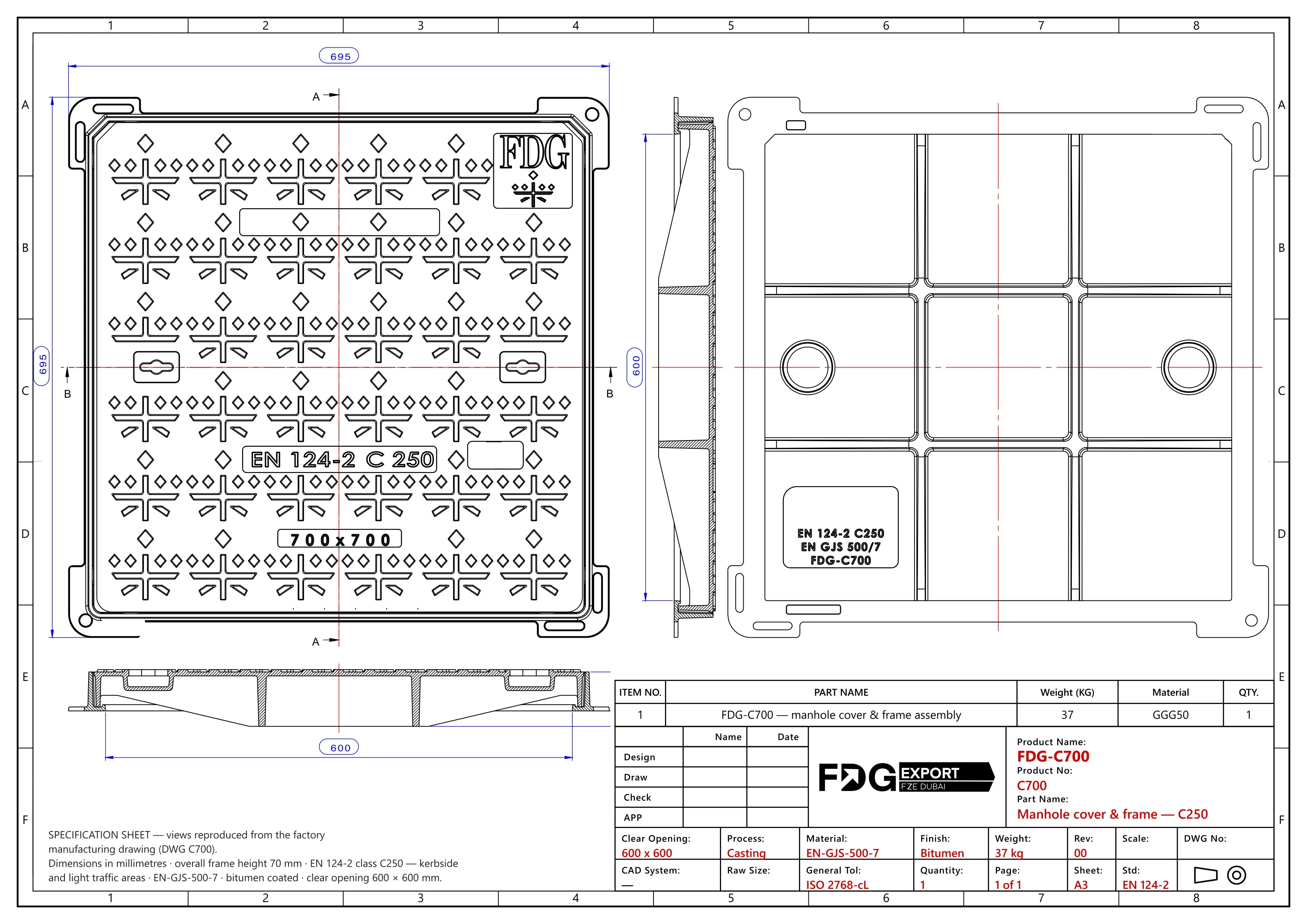 Preview only — contact us for the full drawing or DWG Preview only — contact us for the full drawing or DWG |
| FDG-C800 | 700 × 700 | 795 × 795 | 71 | C250 | 52 | 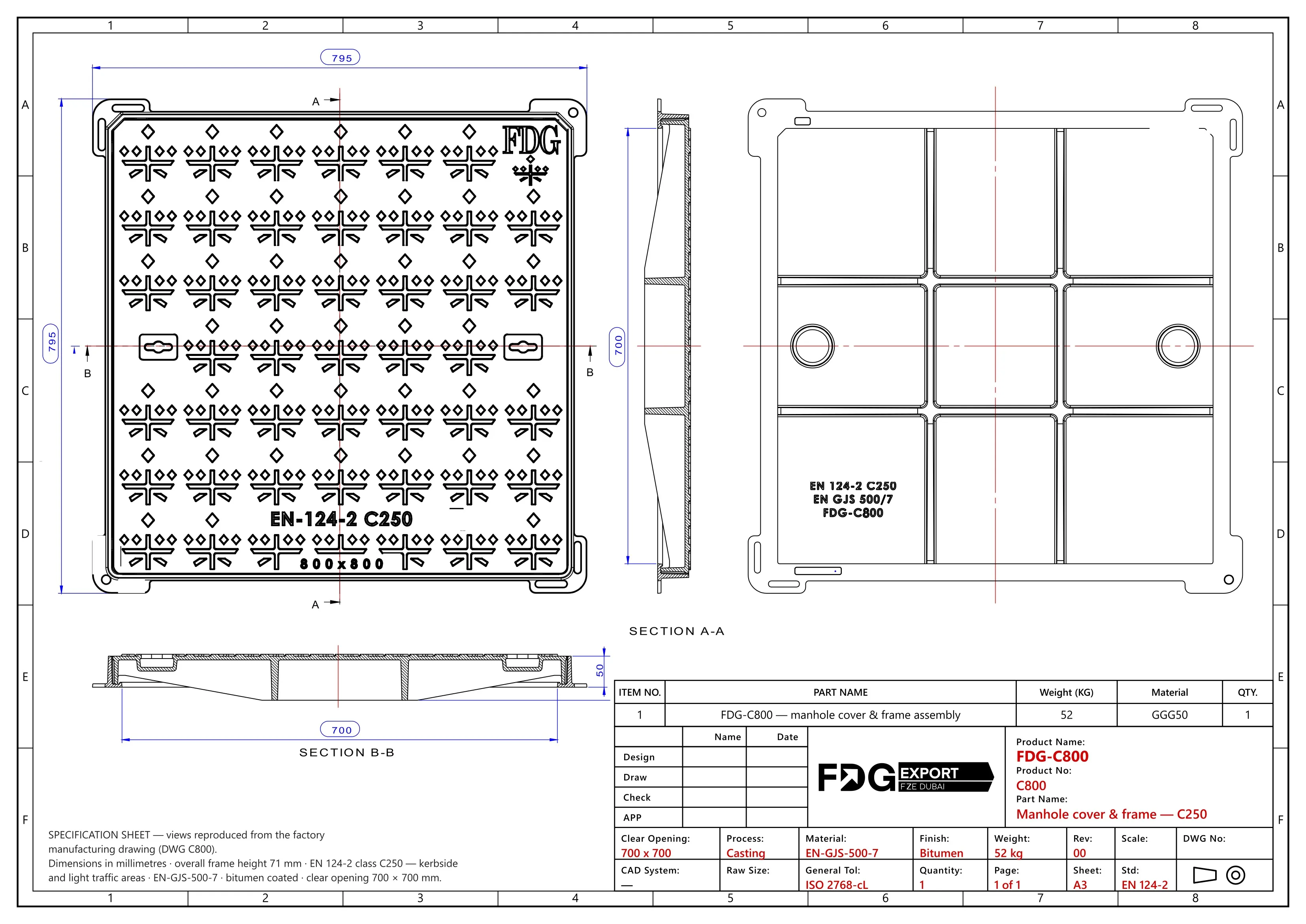 Preview only — contact us for the full drawing or DWG Preview only — contact us for the full drawing or DWG |
| FDG-D400 | 266 × 266 | 400 × 400 | 75 | D400 | 15.6 | 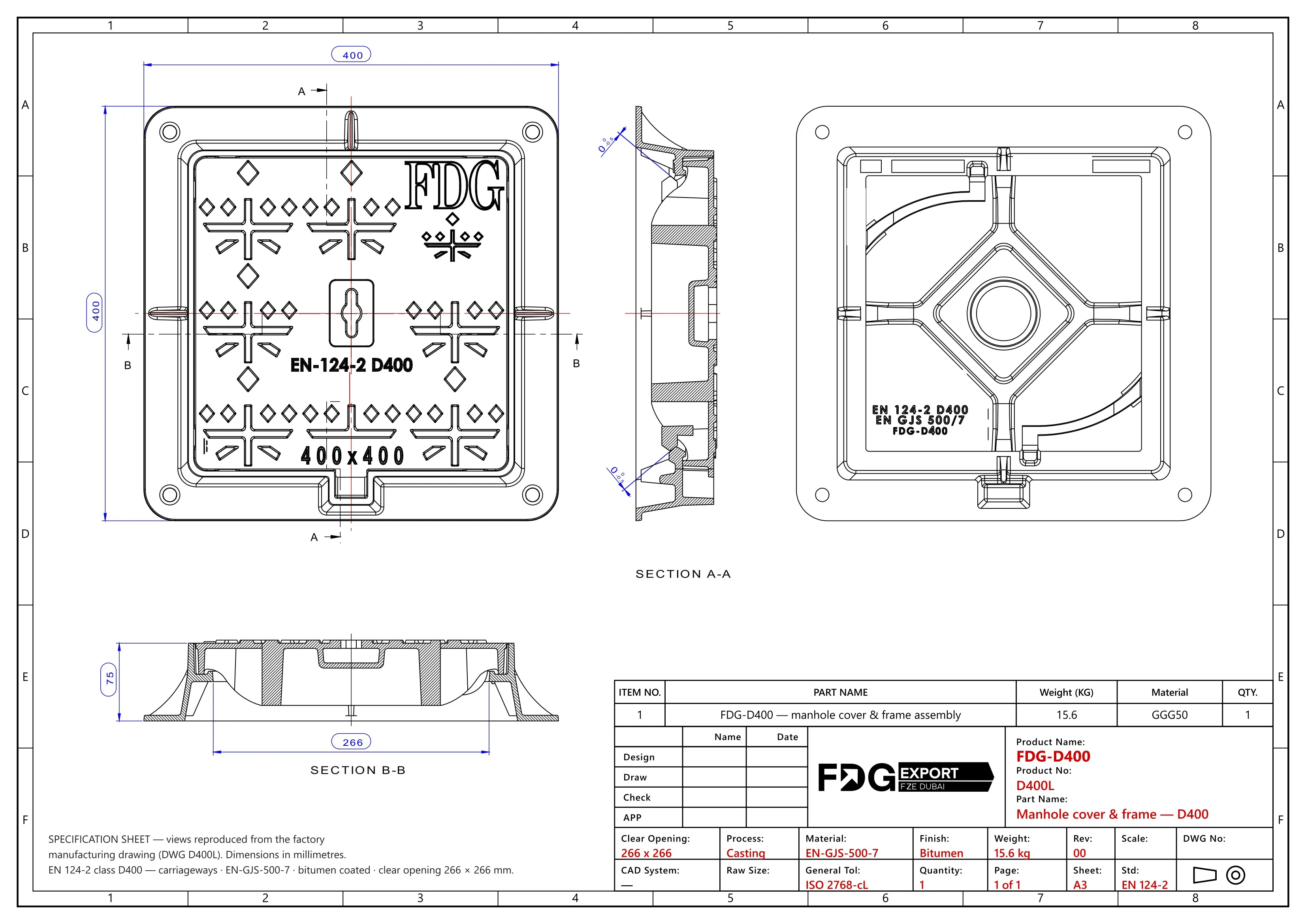 Preview only — contact us for the full drawing or DWG Preview only — contact us for the full drawing or DWG |
| FDG-D500 | 366 × 366 | 500 × 500 | 75 | D400 | 23.8 | 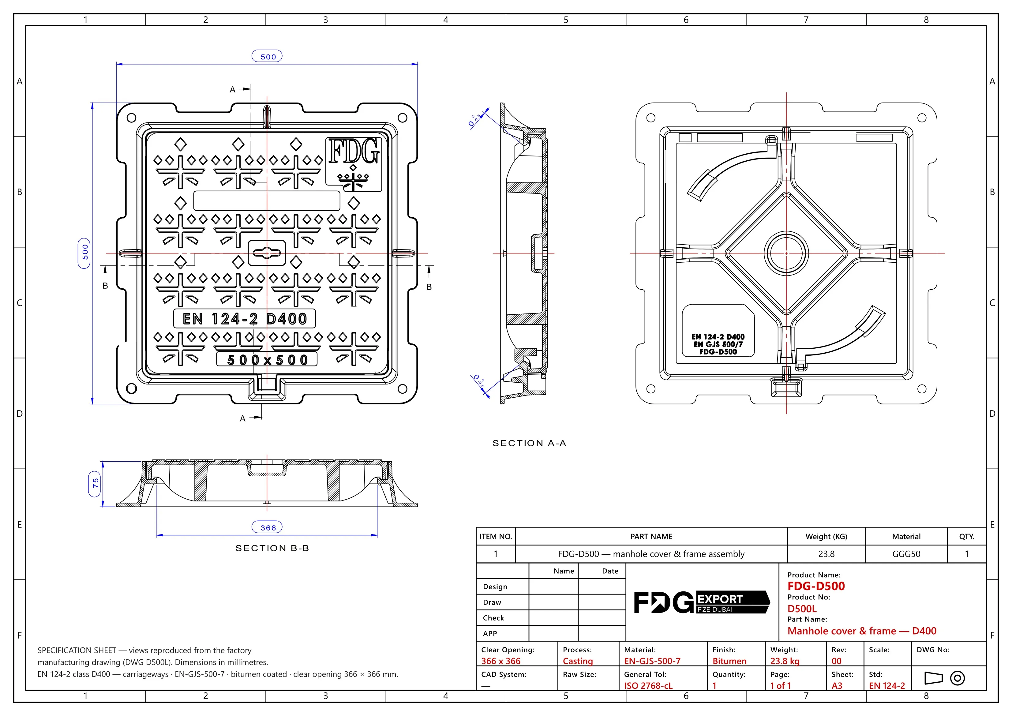 Preview only — contact us for the full drawing or DWG Preview only — contact us for the full drawing or DWG |
| FDG-D600 | 466 × 466 | 600 × 600 | 80 | D400 | 35.8 | 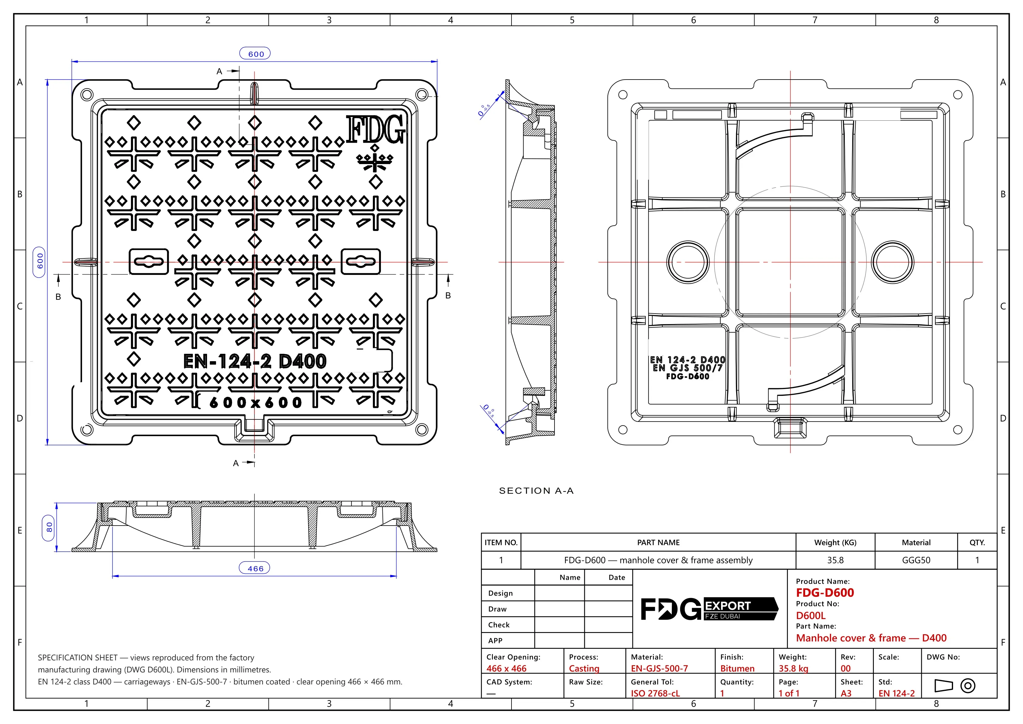 Preview only — contact us for the full drawing or DWG Preview only — contact us for the full drawing or DWG |
| FDG-D700 | 566 × 566 | 700 × 700 | 85 | D400 | 50.5 | 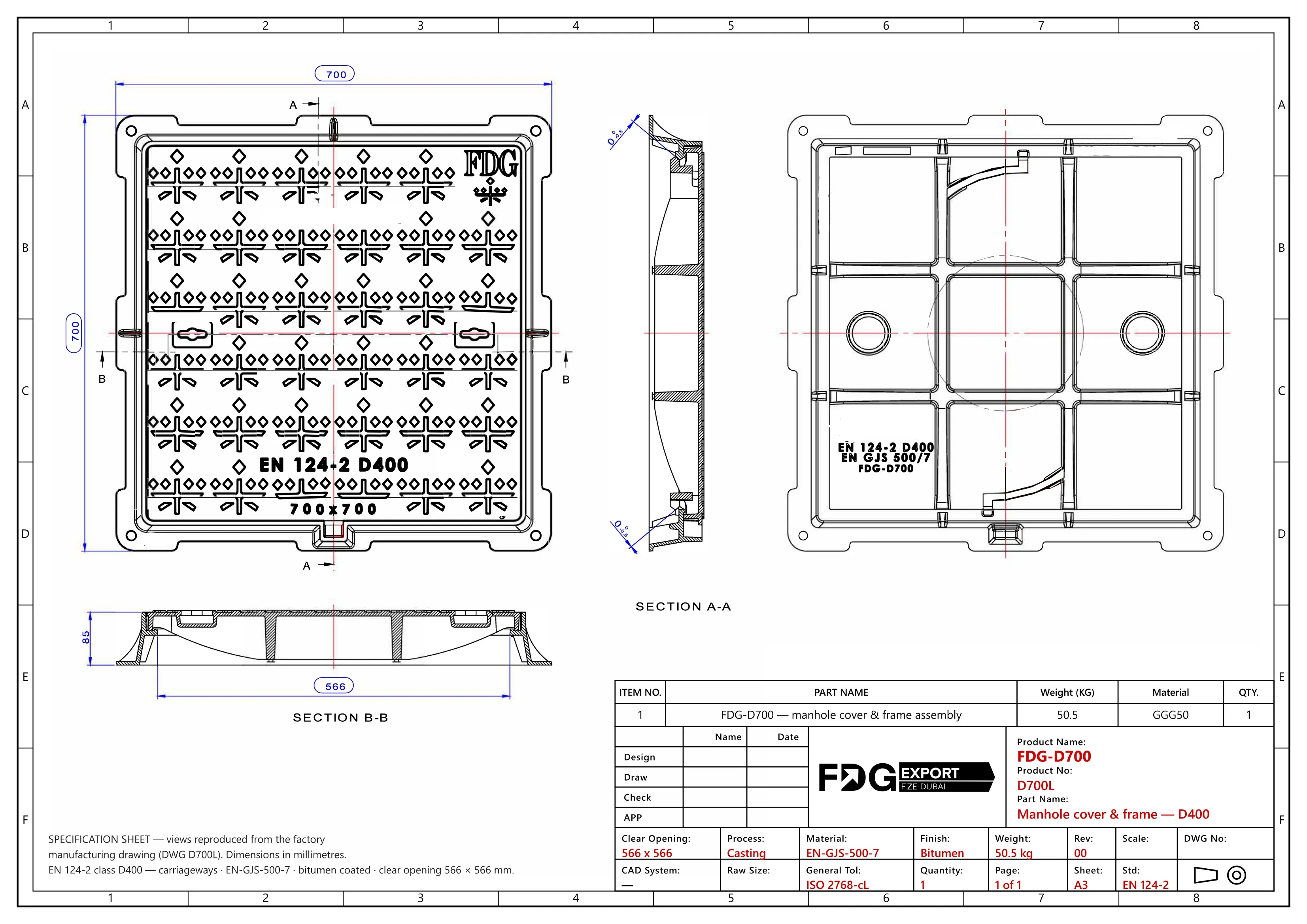 Preview only — contact us for the full drawing or DWG Preview only — contact us for the full drawing or DWG |
| FDG-D800 | 666 × 666 | 800 × 800 | 85 | D400 | 61.5 | 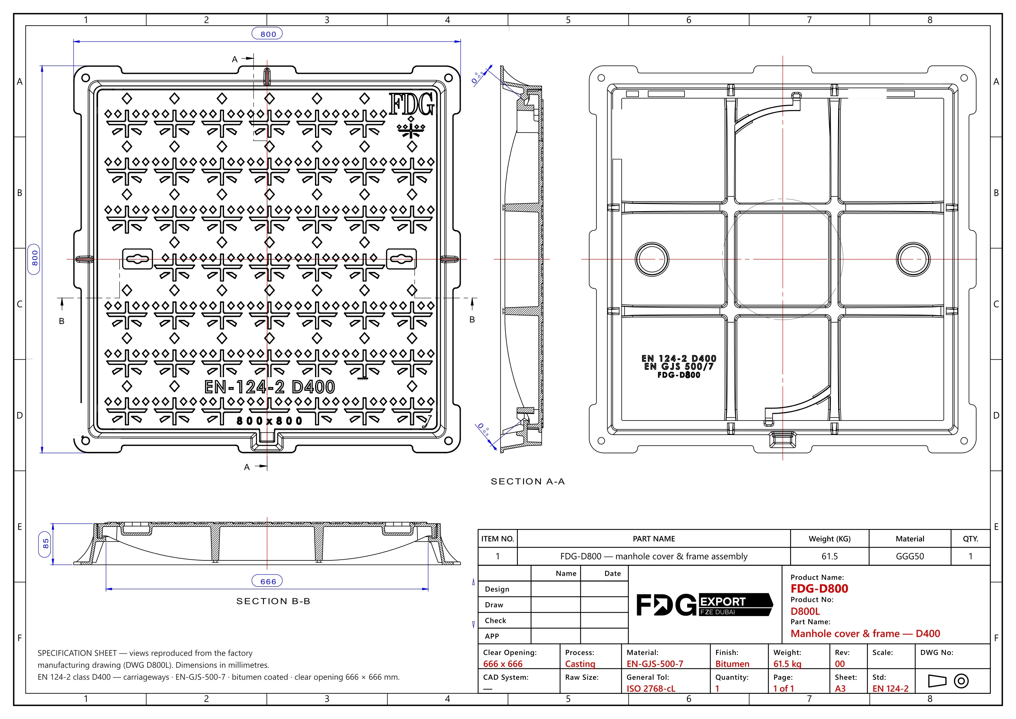 Preview only — contact us for the full drawing or DWG Preview only — contact us for the full drawing or DWG |
| FDG-D900 | 766 × 766 | 900 × 900 | 100 | D400 | 93 | 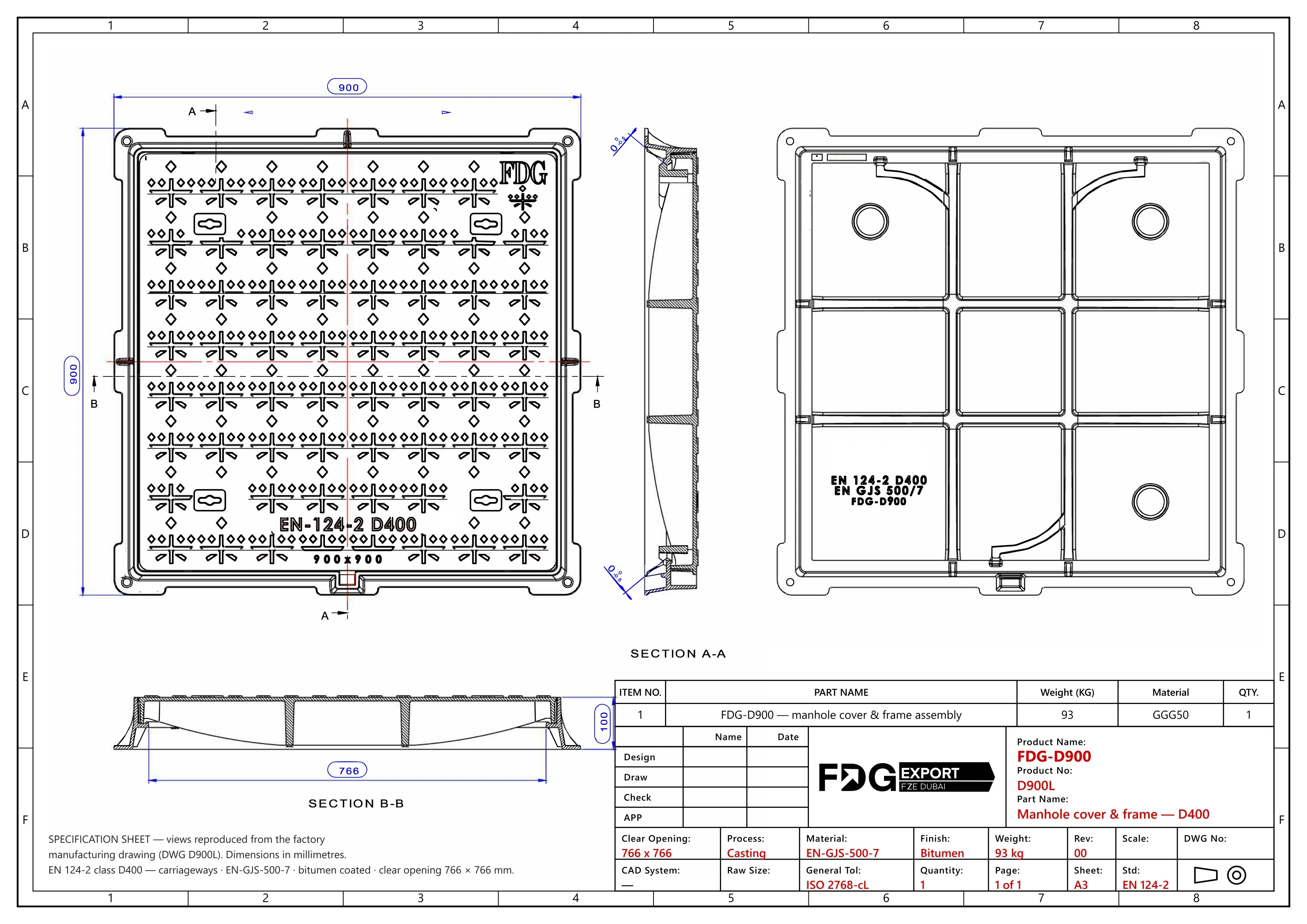 Preview only — contact us for the full drawing or DWG Preview only — contact us for the full drawing or DWG |
Seventeen models to EN 124-2, single-piece covers with matching frames, EN-GJS-500-7 ductile iron, bitumen coated. Models are named for their nominal size — FDG-B300 is the 300 size — and the frame outer given here is the measured dimension, which on the B125 and C250 covers runs 5 mm under the nominal. Frame depth is the overall installed depth read from the section. Full drawings and DWG files are available on request.
Common questions
Specifying manhole covers
- What is the difference between B125, C250 and D400?
- They are EN 124 load classes: B125 is a 12.5 tonne test load for footways and car parks, C250 is 25 tonnes for kerbside and channel areas, D400 is 40 tonnes for carriageways. All three are published here: the GCC range in the 600×600 format, and the international range from 300×300 to 900×900.
- Do the different classes share a frame?
- C250 and D400 share a common frame, 100 mm deep. B125 has its own frame at 38 mm.
- Which is right for a car park?
- B125 covers light vehicle areas. Where delivery vehicles or heavy traffic cross the cover, specify C250 or D400.
- Can you supply sizes other than those listed?
- Yes. The published sizes are the standard range; other clear openings are produced to order.